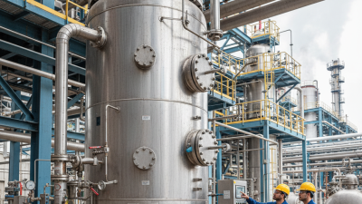
What Are the 2026 Top ASME Pressure Vessel Types? This question matters wherever heat, pressure, and human safety meet. An Asme Pressure Vessel is not merely a steel shell. It is a carefully engineered boundary, often hidden behind insulation, paint, and rotating equipment. Inside, steam, gas, chemicals, or superheated liquid may apply tremendous force.
Process-safety authority Sam Mannan often warned, “There is no such thing as zero risk.” That sentence deserves attention. It reminds engineers that design quality depends on more than code compliance. Material selection, weld inspection, fatigue analysis, corrosion control, and relief-system sizing all influence service life. A small nozzle crack can become a major shutdown. A poorly supported vessel can vibrate for years before failure appears.
This 2026 overview examines the pressure vessel types receiving the most attention across energy, chemical processing, food production, pharmaceuticals, and industrial manufacturing. It considers vertical and horizontal vessels, storage tanks, reactors, heat exchangers, separators, and fired equipment. It also explains how ASME Section VIII divisions affect design expectations, inspection depth, and operating limits.
The categories overlap. That is important. A reactor may also function as a jacketed vessel or heat exchanger. Classification is not always clean. Real projects force difficult choices.
Readers will find practical distinctions, visible design details, and engineering considerations behind each leading type. The goal is not to declare one vessel universally superior. The better question is simpler: which design fits the pressure, temperature, process fluid, inspection plan, and actual operating conditions?
ASME Section VIII applies to vessels operating above 15 psig, whether pressure is internal or external. Common 2026 applications include storage tanks, gas separators, reactors, heat exchangers, and compressed-gas vessels. These designs appear in refining, chemical processing, power generation, and hydrogen infrastructure. The International Energy Agency reported global hydrogen demand reached about 97 million tonnes in 2023. That growth increases demand for properly engineered storage and separation equipment.
Horizontal separators handle gas, liquid, and solid phases inside a single shell. Vertical vessels save floor space but require careful support and wind-load calculations. Jacketed reactors need reliable heat-transfer control, especially during fast exothermic reactions. Shell-and-tube exchangers may also fall within Section VIII when their pressure boundaries exceed 15 psig. However, pressure alone does not settle code applicability. Vessel configuration, service, fabrication method, and local enforcement still matter. This is where many early specifications become too confident.
Tips: Confirm the design pressure, temperature, materials, corrosion allowance, and relief strategy before selecting a vessel type. Check Section VIII exclusions and jurisdictional rules with a qualified engineer. The 2024 Global Hydrogen Review notes that low-emissions hydrogen remains a small share of total supply. That suggests future equipment demand, but forecasts are not guarantees. Field experience still exposes overlooked issues, including cyclic fatigue, insulation damage, and difficult inspection access. Small details matter.
What Are the 2026 Top ASME Pressure Vessel Types?
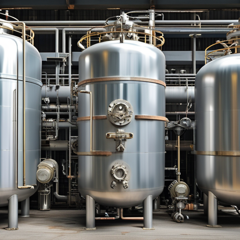
Storage vessels remain central to 2026 pressure vessel planning. Horizontal, vertical, and spherical designs each solve different space and process problems. ASME Boiler and Pressure Vessel Code Section VIII governs many of these vessels. It addresses design, fabrication, inspection, and testing requirements. Fortune Business Insights estimated the global pressure vessel market at about USD 58 billion in 2024. Its forecast indicates continued growth through 2032, supported by energy, chemical, and industrial gas projects.
Horizontal vessels suit sites with limited height and easier ground-level access. Their saddles distribute weight across the supporting structure. Vertical vessels use smaller footprints, which helps crowded processing facilities. However, their taller shells can increase lifting, wind, and seismic design demands. Spherical vessels provide excellent pressure efficiency because stress spreads more evenly across the shell. They require complex fabrication and demanding inspection controls. ASME Section VIII Division 1 and Division 2 provide different design pathways, depending on analysis depth and operating conditions.
The choice is not always obvious. A compact sphere may reduce steel volume but increase construction difficulty. A vertical vessel may save land yet complicate maintenance access. The American Petroleum Institute’s API 2510 guidance also influences LPG storage layout and safety distances. Those distances can change the real project footprint. I have seen preliminary layouts favor the “most efficient” shape, then lose efficiency after platforms, insulation, valves, and emergency access are added. Storage design needs operating data, not only catalog dimensions. Maybe that is the uncomfortable part.
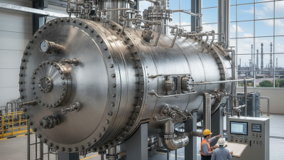
Shell-and-tube heat exchangers remain a leading pressure vessel type under ASME Section VIII rules. Their appeal is practical: strong cylindrical shells, replaceable tubes, and reliable performance under heat and pressure. In refineries, chemical plants, and power facilities, one side may carry steam while the other carries cooling water. A small tube leak can then create a serious cross-contamination risk.
ASME BPVC Section VIII, Division 1, requires design checks for pressure, materials, welding, inspection, and relief protection. Division 2 applies stricter analysis and documentation for more demanding designs. The U.S. Department of Energy identifies heat recovery as a major industrial efficiency opportunity. Meanwhile, Mordor Intelligence’s 2025 market assessment projects the global heat exchanger market to grow from about USD 18 billion in 2025 to more than USD 25 billion by 2030. That growth increases demand for traceable calculations, not just faster fabrication. Real projects still expose weak assumptions. Fouling allowances may be optimistic. Tube vibration can be underestimated.
Tips: Confirm design pressure and temperature on both sides. Check tube-sheet thickness after corrosion allowance. Review material certificates, weld records, and hydrostatic test results. Ask for a clear fatigue assessment when temperatures cycle frequently. Field lessons matter. A clean datasheet cannot replace operating experience.
Process reactors and separators remain central to the 2026 pressure vessel landscape. Reactors manage chemical conversion under controlled pressure and heat. Separators remove gas, liquid, or solids from process streams. Their duties differ, but failure risks are equally serious.
The International Energy Agency’s Global Hydrogen Review 2024 reports that announced low-emissions hydrogen projects could support nearly 49 million tonnes of annual production by 2030. That growth increases demand for reactors, knockout drums, and high-pressure separators. Many hydrogen services involve elevated temperatures and hydrogen embrittlement concerns. Designers should verify material compatibility, weld quality, and inspection access under ASME BPVC Section VIII. Stainless alloys may resist corrosion, yet they are not automatically suitable.
Temperature changes deserve equal attention. A separator shell can experience thermal gradients during startup, shutdown, or depressurization. These gradients may create local stress that simplified calculations miss. ASME design rules help, but process history still matters. Field engineers often review operating cycles, not only nameplate pressure.
Materials selection should consider chloride exposure, sour service, erosion, and cyclic loading. The International Energy Agency’s World Energy Outlook 2024 also highlights continuing investment in industrial decarbonization, where new process conditions may challenge established vessel designs. Some assumptions will age badly. I would question any specification that treats pressure, temperature, and materials as separate decisions. They interact continuously inside the vessel.
What Are the 2026 Top ASME Pressure Vessel Types?
Divisions 1–3: Selecting Rules for Service Above 10,000 psi
Pressure vessels above 10,000 psi demand more than a familiar shape. Autoclaves, intensifiers, compact reactors, and high-pressure separators often require careful code selection. Their geometry, temperature, cyclic loading, and stored energy can change the design path.
ASME Section VIII Division 1 uses established design rules for many conventional vessels. It can suit moderate complexity when pressure cycles remain manageable. Division 2 applies more detailed analysis and stricter examination requirements. It becomes valuable when weight, fatigue, or unusual geometry affects performance. Division 3 focuses on very high-pressure vessels and considers advanced stress evaluation, fracture control, and demanding material behavior.
A pressure value alone should not decide the division. That shortcut is tempting, but incomplete. Engineers should review design pressure, operating cycles, corrosion allowance, weld quality, material toughness, and inspection access. A thick-wall vessel may appear safe while local stress concentrates around a nozzle or closure. Small details matter.
In practical projects, early finite element analysis can expose weaknesses before fabrication begins. However, analysis is not a substitute for sound assumptions or qualified review. The selected division must also match the jurisdiction, certification route, and available manufacturing controls. Sometimes the most efficient vessel is not the lightest one. It is the vessel with clearer inspection, simpler maintenance, and fewer uncertain design decisions.
| ASME BPVC Section VIII Division | Typical Pressure-Vessel Type | Pressure-Service Position | Primary Design Approach | Stress and Fatigue Considerations | Typical Construction Features | Inspection and Examination Emphasis | Typical Applications | Selection Guidance |
|---|---|---|---|---|---|---|---|---|
| Division 1 Rules for Construction of Pressure Vessels |
Conventional pressure vessels, including cylindrical shells, spherical vessels, formed heads, jacketed vessels, heat-exchanger components, and other vessels within the Division 1 scope. | Commonly selected for low-to-moderate pressure service. It can also be used outside the high-pressure range when the applicable design rules and material limitations are satisfied; it is not defined solely by a universal pressure cutoff. | Design-by-rule using prescribed formulas, allowable stresses, minimum thickness requirements, reinforcement rules, and specified details for openings and vessel components. | Primarily based on allowable-stress design and code-specified design formulas. Fatigue evaluation may be required for cyclic service, but the overall rules are generally less analysis-intensive than Division 2 or Division 3. | Often uses conventional welded construction, standard shell-and-head geometries, reinforced openings, flanges, nozzles, supports, and corrosion allowances where applicable. | Required examinations depend on the applicable construction category, joint efficiency, material, weld details, and service conditions. Visual examination and specified nondestructive examination are used as required by the Code. | Storage vessels, process vessels, separators, reactors, filters, boilerside pressure components within scope, and general industrial pressure equipment. | Choose Division 1 when the vessel has conventional geometry and the design can be adequately covered by its rules. For service above 10,000 psi, perform a specific engineering review rather than assuming Division 1 is automatically appropriate. |
| Division 2 Alternative Rules |
Heavily engineered pressure vessels, thick-wall vessels, high-cycle vessels, and vessels with complex geometry or demanding fatigue requirements. | Suitable for higher-pressure or more demanding service than many Division 1 designs. The practical pressure range depends on geometry, materials, temperature, loading, fatigue life, and the detailed design analysis. | More rigorous design-by-analysis and design-by-rule requirements than Division 1. The rules address stress classification, local stresses, design conditions, openings, welded details, and fabrication controls in greater detail. | Requires more detailed evaluation of primary, secondary, and peak stresses where applicable. Fatigue assessment is a major consideration for vessels exposed to repeated pressure, thermal, or mechanical cycles. | May use thicker sections, higher-strength or specially qualified materials, refined nozzle designs, controlled weld details, and geometries optimized to reduce stress concentration and fatigue damage. | Typically involves more stringent material, welding, qualification, inspection, nondestructive examination, and documentation requirements than Division 1. The authorized inspection process must follow the applicable Code provisions. | High-pressure process equipment, cyclic reactors, high-temperature vessels, large critical vessels, and equipment where fatigue or local stress is important. | Consider Division 2 when Division 1 thicknesses, fatigue margins, geometry limits, or analysis requirements become impractical. It may be a suitable alternative below or around the 10,000 psi range, but the actual design pressure is not the only selection factor. |
| Division 3 Alternative Rules for Construction of High Pressure Vessels |
High-pressure vessels specifically engineered for very high-pressure service, including thick-wall cylinders, autofrettaged vessels, multilayer vessels, and specialized high-pressure chambers. | Intended for high-pressure applications, commonly associated with design pressures above 10,000 psi. The exact applicability must be confirmed against the current Code edition, vessel configuration, materials, and service conditions. | Specialized high-pressure design rules addressing pressure-induced stresses, thick-wall behavior, local effects, openings, closures, autofrettage where used, and other features characteristic of high-pressure construction. | Requires detailed consideration of through-wall stress distributions, stress concentration, fracture-related behavior, cyclic loading, fatigue, and the effects of manufacturing processes on structural integrity. | May include thick monoblock cylinders, layered or wire-wound construction, shrink-fit components, high-pressure closures, specially designed seals, autofrettaged sections, and carefully controlled transitions. | Places strong emphasis on material traceability, qualified manufacturing processes, weld and fabrication controls where applicable, dimensional verification, nondestructive examination, pressure testing, and documented inspection records. | High-pressure research equipment, hydrostatic testing systems, high-pressure chemical processing, supercritical-fluid equipment, hydraulic intensifiers, and specialized industrial or scientific pressure chambers. | Start with Division 3 when the design pressure is above 10,000 psi or when thick-wall and high-pressure effects dominate the design. Confirm that all components, closures, materials, testing, and fabrication methods meet the applicable Division 3 requirements. |
| Division 1 vs. Division 2 | Conventional vessel compared with an engineered alternative-rule vessel. | The dividing line is not determined by pressure alone. Weight, fatigue life, material strength, geometry, temperature, and fabrication capability also matter. | Division 1 generally relies more heavily on prescribed formulas; Division 2 requires a more detailed and analysis-oriented design process. | Division 2 is generally better suited to significant cyclic loading and detailed fatigue evaluation, subject to the specific Code requirements. | Division 2 can sometimes reduce unnecessary thickness through a more refined analysis, although fabrication and qualification requirements may increase. | Division 2 usually requires a higher level of engineering documentation and quality-control coordination. | Used when the vessel is too demanding for an economical or technically suitable Division 1 design but does not necessarily require Division 3. | Compare the complete lifecycle cost, engineering effort, fabrication capability, inspection plan, fatigue life, and operating envelope before selecting the Division. |
| Division 2 vs. Division 3 | Advanced pressure vessel compared with a purpose-designed high-pressure vessel. | Division 3 is the more direct candidate for service above 10,000 psi, while Division 2 may be appropriate for demanding pressure service that remains within its applicable rules. | Division 3 includes specialized provisions for high-pressure vessel behavior and construction that may not be adequately represented by a conventional Division 2 approach. | Both require careful fatigue and stress evaluation; Division 3 additionally focuses on the severe stress gradients and failure consequences associated with high pressure. | Division 3 designs may require specialized closures, layered construction, autofrettage, high-strength materials, or other controlled high-pressure techniques. | Division 3 typically demands especially strong control of materials, processes, examination, testing, and documentation because stored energy and failure consequences increase rapidly with pressure. | Used for specialized systems where pressure, wall thickness, cyclic duty, or stored energy makes ordinary vessel construction unsuitable. | For pressure above 10,000 psi, evaluate Division 3 first, then verify whether the selected materials, geometry, manufacturing route, fatigue life, and testing plan are explicitly permitted and adequate. |
| High-Pressure Vessel Selection Checklist | Any vessel operating at or near high-pressure conditions. | Confirm design pressure, maximum allowable working pressure, design temperature, operating cycles, pressure transients, and vacuum or external-pressure cases. | Identify the governing Code edition and applicable Division before detailed design. Check whether the vessel, component, closure, piping interface, and accessories are all within the selected Code scope. | Evaluate fatigue, fracture-related risks, thermal gradients, local stresses, pressure cycling, startup and shutdown events, and credible overpressure conditions. | Verify material toughness, compatibility, weldability, heat treatment, corrosion allowance, seal design, closure integrity, and dimensional tolerances. | Establish inspection points, nondestructive examination methods, pressure-test requirements, calibration controls, records, and authorized inspection involvement. | Particularly important for systems where a pressure boundary failure could cause significant personnel, environmental, or equipment hazards. | Treat “above 10,000 psi” as an engineering screening point, not a substitute for a formal Code applicability review. The current ASME BPVC edition and project-specific jurisdictional requirements govern the final selection. |